OBD Development Kit
OBD 개발 키트는 OBD 버스 인터페이스에 대해 빠른 개발을 위해 modular 개발 시스템으로 디자인되었습니다. Interconnect Board, 탈부착할 수 있는 3가지 모듈 (Power, OBD drivers, and STN11xx), 그리고 OBD cable 로 구성되어 있습니다.
As-shipped, the kit is a fully functioning OBD-II to USB interface that supports all OBD-II protocols and works with any ELM327-compatible software.
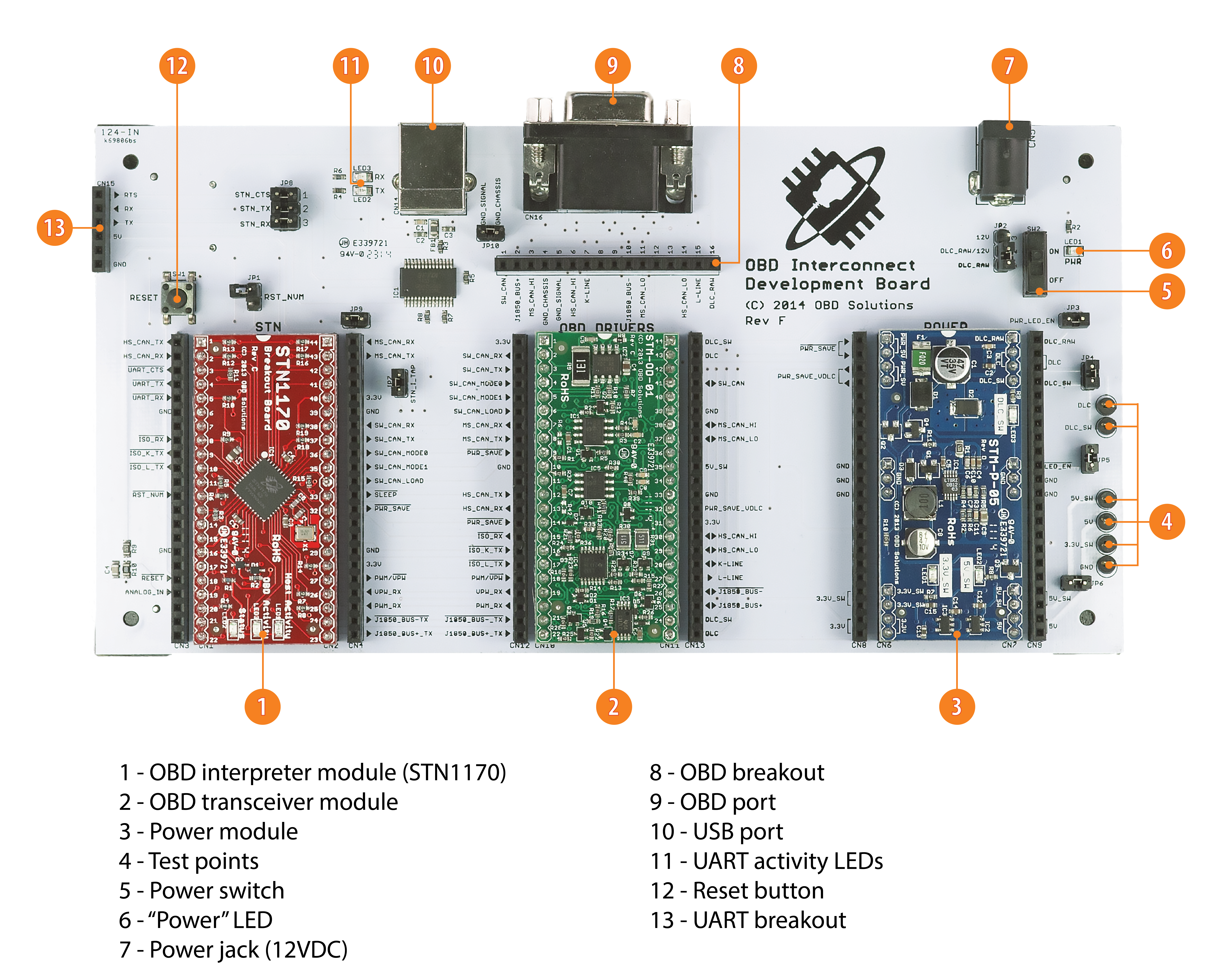
The Interconnect Board features UART and USB interfaces, an OBD breakout with access to all all 16 OBD port lines, three module slots with breakout headers, and a number of configuration jumpers and test points.
The unique modular design offers considerable flexibility, allowing engineers to quickly evaluate, prototype, and verify the major circuit blocks.
구성품
OBD Interconnect Development Board with 3 modulesCable, J1962M to DB15 (HI-DM)USB Cable, 6ft(Power Supply : 12VDC @ 3.5A 100-240VAC (3-Prong) 는 선택 사항입니다. 국내 판매되는 타사 Power Supply 사용 가능합니다.)
Features
1. Modular design - Interconnect Board
- STN Breakout Module
- OBD Driver Module
- Power Module
- 2. ELM327-compatible command set
- 3. Breakout headers for all module pins
- 4. 16-pin OBD breakout header
- 5. UART and USB interfaces (FT232RL/Virtual COM Port)
- 6. Test points for measuring voltage
- 7. Tap points for measuring current
- 8. Configurable sleep/wakeup functionality
- 9. Can be powered from OBD Port, or the optional 12VDC power supply
Support for all legislated OBD-II protocols:
- SAE J1850 PWM
- SAE J1850 VPW
- ISO 9141-2
- ISO 14230-4 (KWP2000)
- ISO 15765-4 (CAN 250/500 kbps, 11/29 bit)
Support for non-legislated OBD protocols:
- ISO 11898 (raw CAN)
- SAE J1939 (cable not supplied)
- Single Wire CAN (SW-CAN) - GM proprietary network
- Medium Speed CAN (MS-CAN) - Ford proprietary network
Schematics
- OBD Interconnect Development Board
- STN1170 Breakout Module
- STN1110 Breakout Module
- OBD Driver Module
- Power Module
Drivers
- USB Drivers (Virtual COM port)
Documentation
- Microchip MASTERs slides (“Interfacing with Vehicle Networks: Best Practices”)
- Microchip MASTERs lab manual
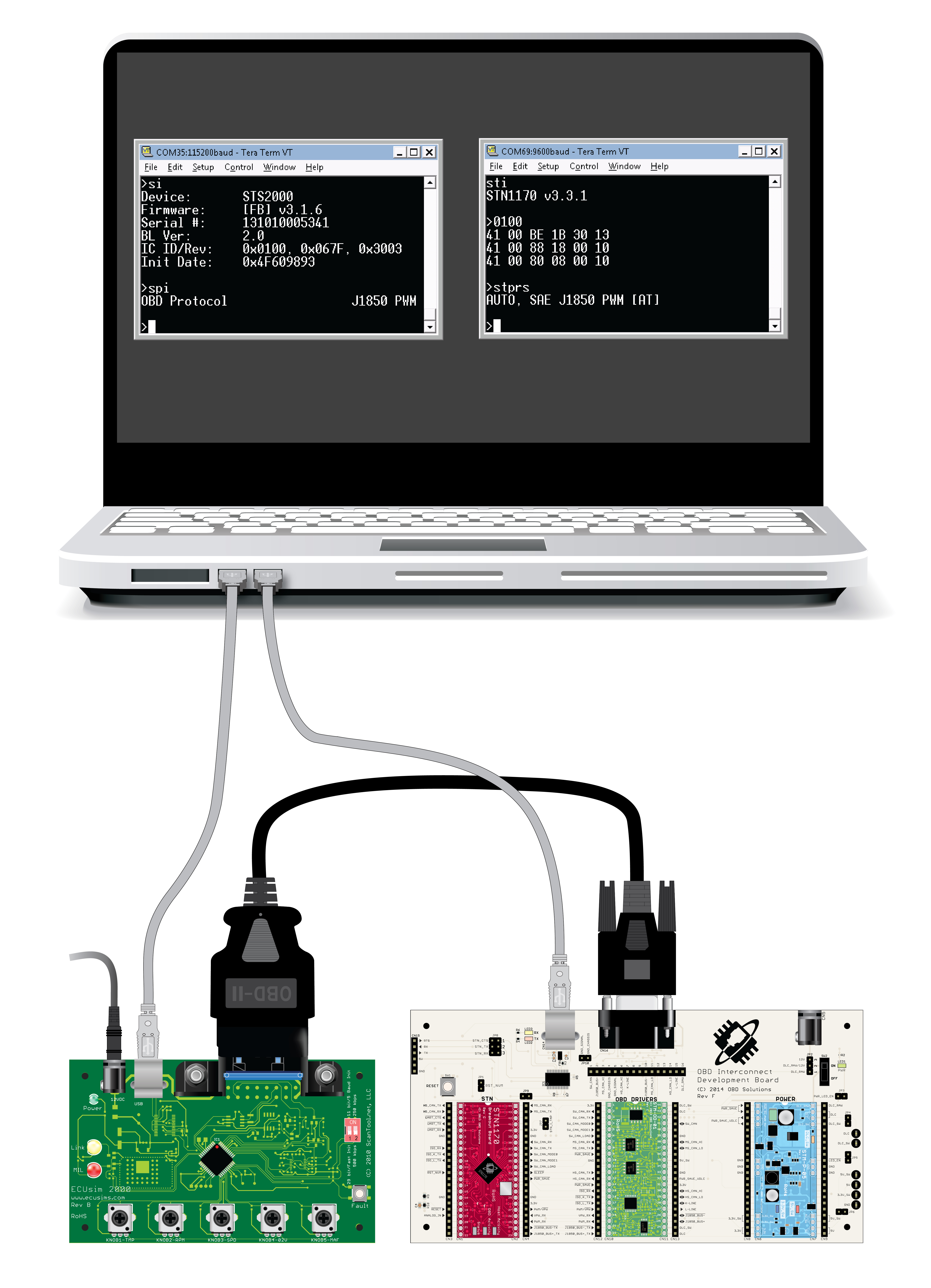
Connection Diagram

Shown with optional ECUsim 2000 and laptop (not included). For more information see the Lab Manual
User Interface Diagram


